Demostration of the Tesla Coil
A Tesla coil is a type of electrical circuit that is used to produce high-voltage, high-frequency alternating current electricity. It was invented by Nikola Tesla in th... View MoreDemostration of the Tesla Coil
A Tesla coil is a type of electrical circuit that is used to produce high-voltage, high-frequency alternating current electricity. It was invented by Nikola Tesla in the late 19th century, and is still used today in a variety of applications, including wireless power transmission, lighting displays, and educational demonstrations. The Tesla coil consists of a primary coil and a secondary coil, each of which is connected to a capacitor. When a high-voltage current is applied to the primary coil, it induces a current in the secondary coil, which in turn generates a high-voltage, high-frequency current. The circuit also typically includes a spark gap which help to create a high voltage pulse that is used to excite the secondary coil.
Today, we will explore a Tesla coil kit, one put together and experiment with it.
Project Video https://rumble.com/v27juq3-tesla-coil-presentation.html
Mini Tesla Coil Kit https://amzn.to/3kOYdRs
Music Tesla Coil https://amzn.to/3XMEZug
Tesla Coil Wireless Transmission Demonstration Tool Lamp Glow Tube Neon Light https://amzn.to/3DmXPzX
Please like and share this Video. Thank you and I hope you enjoy these Projects and share them with others as well. If, you find it in your heart and would like to buy me a cup of coffee, that would be awesome. https://www.buymeacoffee.com/guardianwill or if you would like to help in our next projects we sure could use the help. https://gofund.me/27c87809
Thank you in advance for your kindness and generosity, it definitely means a lot.
Tesla Coil Presentation
Demostration of the Tesla Coil A Tesla coil is a type of electrical circuit that is used to produce high-voltage, high-frequency alternating current electricity. It was invented by Nikola Tesla in the
A/C Power, Philadelphia Experiment, Radio, Coil, Power. What do all these things have in Common? They were either inventions or things Nikola Tesla participated in or created.
Nikola Tesla (1856-19... View MoreA/C Power, Philadelphia Experiment, Radio, Coil, Power. What do all these things have in Common? They were either inventions or things Nikola Tesla participated in or created.
Nikola Tesla (1856-1943) was a Serbian-American inventor and electrical engineer who is best known for his development of alternating current (AC) electricity. He also created the Tesla coil, which is an electrical resonant transformer circuit used in radio technology. Tesla's work in AC electricity led to his development of the Philadelphia Experiment, which was an attempt to create a cloaking device to make warships invisible.
Nikola Tesla was a brilliant inventor and a lover of music. He believed that music and frequencies were the key to unlocking the mysteries of the universe. He used this knowledge to create some of his most remarkable inventions, such as the alternating current system, the Tesla Coil, and the rotating magnetic field. He used music and frequency to study resonance and harmonics. He experimented with sound waves and how they interacted with electricity, often creating spectacular displays of light and sound. He also believed that music could be used to heal and energize the human body. Tesla used his knowledge of music and frequency to advance his inventions, ultimately leading to some of his most famous breakthroughs.
Video Project https://rumble.com/v26vr5l-tesla-and-the-tuning-fork-experiment.html
2 pack tuning fork https://amzn.to/3XQnJnB
boX 440HZ Tuning Fork https://amzn.to/3J8ZEnQ
Thank you and I hope you enjoy these Projects and share them with others as well. If, you find it in your heart and would like to buy me a cup of coffe, that would be awesome. https://www.buymeacoffee.com/guardianwill or if you would like to help in our next projects we sure could use the help. https://gofund.me/27c87809
Thank you in advance for your kindness and generosity, it definately means a lot.
Tesla and the tuning fork experiment
Tesla and the tuning fork experiment
A/C Power, Philadelphia Experiment, Radio, Coil, Power. What do all these things have in Common? They were either inventions or things Nikola Tesla participated in or created. Nikola Tesla (1856-1943)
If you all are enjoying the projects and we have some new exciting projects planned for this new year maybe, just maybe you would be interested in supporting us with a cup of coffee... Thanks for con... View MoreIf you all are enjoying the projects and we have some new exciting projects planned for this new year maybe, just maybe you would be interested in supporting us with a cup of coffee... Thanks for considering.
https://www.buymeacoffee.com/guardianwill
William Middleton
Hey, I just created a page here and if you wish to support me with a simple cup of coffee that would be awesome. Me and the boys say a mighty THANK YOU!
easy power box putting together with boys
You may not need a full solar generator but it would be nice to have an emergency small power box with dual falshlights, usb and 12v sockets. Take this project and build it with your child for some of
Ever wonder how an inverter actually works by changing DC power to AC pure sign wave inverter? I found this video informational.
https://youtu.be/qVeERT4nyz8
Inverters, How do they work?
Inverters have taken a prominent role in the modern technological world due to the sudden rise of electric cars and renewable energy technologies. Inverters convert DC power to AC power. They are als
https://rumble.com/v1srndz-redodo-review-and-quick-power-block.html
Product Review Redodo 12ah battery
Redodo Power formally zooms has been reviewed and torn down before and proved to be a solid lif... View Morehttps://rumble.com/v1srndz-redodo-review-and-quick-power-block.html
Product Review Redodo 12ah battery
Redodo Power formally zooms has been reviewed and torn down before and proved to be a solid lifepo4 battery storage investment.
Find them here: https://www.redodopower.com/.../redodo-12v-12ah-lithium... Use the code Jack3 for 3% off their already low price.
Amazon redodo power 12ah battery https://amzn.to/3tfrA0c
Charger, though you can use a 10 amp lifepo4 battery charger as well for the 12ah battery https://amzn.to/3htBuc8
Battery terminal connector https://amzn.to/3fO8wmC
USB connector via alligator clips https://amzn.to/3A0Erau
We will be using this to have the boys put together a simple but useful power box. We already found a box simply at walmart with their Plano tool box and is watertight and a nice handle. Stay Tuned...
If you can help, we would truly appreciate and need it -- Thank you https://gofund.me/5b4a16c6 Any little bit helps and we truly are grateful.
These items are listed for your convenience to see the parts and get an idea. If you choose to purchase I do earn a few cents but has no additional cost to you. Several items listed I am displaying because they are where I found the item or its cheaper as well.
redodo review and quick power block
Product Review Redodo 12ah battery Redodo Power formally zooms has been reviewed and torn down before and proved to be a solid lifepo4 battery storage investment. Find them here:
https://www.redodopow
https://rumble.com/v1scmjp-finished-105-battery-pack.html
Finishing touches from our 105 ah lifepo4 battery build. Here we show how we put it into a case to represent what a normal car battery would ... View Morehttps://rumble.com/v1scmjp-finished-105-battery-pack.html
Finishing touches from our 105 ah lifepo4 battery build. Here we show how we put it into a case to represent what a normal car battery would look like.
Unboxing and preparing 105 ah battery How to video https://rumble.com/v1pccqv-overkill-solar-bms-and-100ah-prismatic-from-18650batterystore.html
How to wire up heating pads Video https://rumble.com/v1hmhce-connecting-up-battery-heater-circuit.html
Parts Used for this entire project
Lifepo4 Battery Cells https://www.18650batterystore.com/products/eve-lf105 -- Not Sponsored
Overkill Solar BMS https://overkillsolar.com/product-category/12v-bms/
Wago Lever Nuts https://amzn.to/3tbDW9y
14 Gauge Flexible Silicone Electrical Stranded Wire https://amzn.to/3fIqRS3
Electric Heater Plate https://amzn.to/3DMkaGH
Group 24 Snap-Top Battery Box https://amzn.to/3WJyzMD
Premium High Current 5/16” Feed-Thru Panel Battery Terminal https://amzn.to/3NJ9TQ6
Mini Fuse Kit 12v https://amzn.to/3t9Swyv
Digital Temperature Controller Board https://amzn.to/3DMD3td
If you can help, we would truly appreciate and need it -- Thank you https://gofund.me/5b4a16c6 Any little bit helps and we truly are grateful.
These items are listed for your convenience to see the parts and get an idea. If you choose to purchase I do earn a few cents but has no additional cost to you. Several items listed I am displaying because they are where I found the item or its cheaper as well.
#educate #Solar #portable #generator #youth #science #project #build #lifepo4battery #exhaust #fan #temperature_controller #batteryevo #renogy #victron #overkillsolar
finished 105 battery pack
Finishing touches from our 105 ah lifepo4 battery build. Here we show how we put it into a case to represent what a normal car battery would look like. Unboxing and preparing 105 ah battery How to vid
The only thing available was No power connections to the campsites -- who cares we brought our own power...
6 month review and illustrate how to build mini solar generator
Here we will give a brief review of the first project Mini Solar Generator. Instructions can be found at https://wimkin.com/minisolarg... View More6 month review and illustrate how to build mini solar generator
Here we will give a brief review of the first project Mini Solar Generator. Instructions can be found at https://wimkin.com/minisolargenerator/
It is surely a nice project that can be completed in just a few hours and the children do learn quite a bit from it and best of all -- its a useful project that you can use throughout the house or back yard or camp ground or long trips.
If you can help, we would truly appreciate and need it -- Thank you https://gofund.me/5b4a16c6 Any little bit helps and we truly are grateful.
Video https://rumble.com/v1hmw4f-6-month-review-and-illustrate-how-to-build-mini-solar-generator.html
Mini Solar Generator Project
Mini Solar Generator Project. 1 member. This group will have information on How we are sharing our science project in building a truly usable Mini Solar Generator. Fun for the family, child or adult
For those wondering, we found a small ottoman slip cover that fits nicely over it to keep things out while not in use.
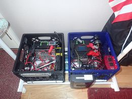
Here is a picture of our first solar generator the boys and I did for science project. We have since then made some modifications to it on the right. The left is our second one we built to write this ... View MoreHere is a picture of our first solar generator the boys and I did for science project. We have since then made some modifications to it on the right. The left is our second one we built to write this lesson plan.
Change connect solar controller, ac charger and inverter.
After testing the prototype out we found that the USB powered LED Light directly wired to 12 v was getting too hot. If you chose to use the ... View MoreChange connect solar controller, ac charger and inverter.
After testing the prototype out we found that the USB powered LED Light directly wired to 12 v was getting too hot. If you chose to use the usb into the solar controller you are fine for it works flawlessly with the USB 5v connection from the usb output from the solar controller. It is also thin enough we will be able without removing it for the next important consideration. If you have cut the wires and prepared it to be connected to the switch for safety reasons I will have a different recommendation
6" 12v LED Light. https://amzn.to/3ls6PKW
Follow the same instructions after removing the LED light, only if you have placed it. Take the 6" LED and position it so it is closer to the switch for the light. And use zip ties to secure after drilling the holes for the wire to be connected.
Next, We should have but just to be sure we will be connecting the inverter to the side front right of the crate and need to make sure it is clear of the master switch. If it is too close, we will need to move the master switch over until it is clear of the inverter. Follow the same procedure with the master switch, it is a bit easier, just unbolt, redrill the hole where it is clear and reassemble and plug the wire spades back in.
The reason it is nice to have everything in front that protrudes is that even though this finished product isn't too heavy the children especially have a tendency to lean it against their body when carrying. You can see in a photo below for an example of what I mean and no need to worry about turning on the master switch if it was in the back of the crate.
Next, lets connect up the solar charger to the fuse box. When we connect the solar charger, no matter where you do it should always have power from the battery. If you plug in the solar panel to the solar generator first before it has power from the battery you can damage the solar controller. Before we actually secure the controller to the crate we will make all necessary connection to it. It is much easier to connect the cables to the controller while it is loose. The controller will eventually be placed in the front left part of the crate.
Amazon Solar Controller https://amzn.to/38FkRpB
Renogy Site https://www.shareasale.com/u.cfm?d=696801&m=96785&u=3236126 Save 10% use coupon code RenogySolar10
Solar Panel SAE Connector https://amzn.to/3G39ofT
SAE adapter Cable https://amzn.to/3LpNS61
What we will do is to take the connection for the sae plug in and using 4 zip ties attach it to the crate as like in the example below. The wire will be close to the bottom of the inner part of the crate and let it rest their.
Next, we will take our red 10 gauge wire and with the controller aprox where it will be secured measure the distance with a little slack going from the positive battery connector of the controller, which should be the middle 2 plus and minus with a battery symbol. This end can be striped and then measure to the first positive screw on the fuse block. Leave a little slack and then cut the wire. Take your yellow #8 ring connector and after stripping the wire crimp on the connection. The renogy company always sends out their controllers in a closed state so the first time you set it up you need to turn it to the left as in loosening a bolt or screw. Then, when wide open take the end of the wire and place it into the slot under the battery symbol marked plus +. When the wire is all the way in with the insulation only showing, take your screwdriver and tighten to a snug but not too tight. It should hold the wire in when a small tug is given. Now take the end we crimped and unscrew one of the bolts next to a slot for a fuse as illustrated in the below picture and then take the ring, place the bolt back in and tighten.
As you noticed you can use a regular screw driver on the fuse block but you will need a precision screwdriver to loosen or tighten the screws on the controller. If you don't have one your local Walmart should have a set quite reasonable.
Now repeat the same for the battery connection using the black wire and across the left side of the fuse block you will see all 6 negative spots. Choose one and unscrew and after stripping/crimping a ring on screw it on. There should be no live connection as of yet because there is no fuse.
Now we can take the sae plug in and trim both positive (red) and negative (black wires of the end of it and then connect them to the controller under the symbol representing a solar panel. These should be the furthest from the usb connections on the controller. When all complete, we will be ready to put in our first fuse. Find a 15 amp fuse and next to the red wire connected to the fuse block you will see a little opening to place the two metal stems of the fuse into it. Press firmly to seat the fuse. You can see how I secured the controller, in the one end I bolted it to the crate and the other end I used a small zip tie.
Next, lets work on the AC Charger. The end we are concerned about is the one with the alligator clips on. We want to Trim the clips off. If you save a few inches of wire to the clips you can reuse these for something else. Strip the ends and using the yellow ring connectors strip and crimp them on both wires. Take the red wire and make the next connection to the fuse block for positive and then take the black wire after connecting the ring connector and then make the connection to the negative bus bar making sure there is ample wire to have a little slack. Take another 15 amp fuse and place it in the slot next to the red wire you just connected. We are again now live.
Here is the last part we will either use 10 gauge, the remaining we will use the 12 gauge wire. We will now connect the Inverter. Exciting cause we now get to use the power from the battery. I cheated a little and ordered allready crimped wires to make this connection.
8 gauge 2 ft power cable https://amzn.to/3MBnU0T
As you can see, the connectors from the inverter will be on the bottom thus securing it to the crate first will only make our job harder. So Take one end of the red wire and tape it to the bottom with the red post on the inverter taking a stretching the wire across to the fuse block to the next positive connection. Here we will move the inverter into place and the other hand stretching the wire allowing slack in the wire to make the connection. Cut the wire when happy. Take one end and place a ring that fits the positive post and strip/crimp fand then take and attach it to the inverter.
As you can see, having the two cables already made just simplified this and saved us some wire.
Repeat for the negative following the same protocol we have been using the black to the negative bus bar and make connection. Locate a 30 amp fuse and plug it in and now we are live.
As you can see I used to bolts to hold the inverter in place with ample room to reach and plug things into it. Then I took 2 zip ties and secured the bottom and middle of the inverter as well. Feels real solid.
Now I hope you will read the manual to the controller and to the ac charger. Each needs to be set to your chosen battery chemistry type and there are other settings you may wish to set. Take time to set these up before using them. If the master switch is on and you turn on the inverter it should start up. Just a not. If you leave the inverter on it will use precious energy from the battery in small amounts but everything counts. Also, when not in use or charging turn the master switch off and the battery will stay idle besides for the very little the volt meter draws.
If you haven't charged your battery yet, remember to set the ac charger to the correct battery chemistry and when done just plug it in it should be charging 🙂
If you can help, we would truly appreciate and need it -- Thank you https://gofund.me/5b4a16c6 Any little bit helps and we truly are grateful.
The next step should be final. We will connect the DC usb, car sockets and lights up.
Connecting Battery to Master Switch to Fuse block.
For those wishing to add a fuse holder we will illustrate where we would add an additional amount of safety to the system as well. Now is getting t... View MoreConnecting Battery to Master Switch to Fuse block.
For those wishing to add a fuse holder we will illustrate where we would add an additional amount of safety to the system as well. Now is getting to the exciting part, actually putting things together. First, this post will deal with making the system active by connecting the battery to the master switch and then to the fuse block.
While it has been safe until now, we must remember the battery is alive and has plenty of juice in it to cause harm. The tools we use should be insulating so that the metal (conductive) parts of the tool will not cause a spark if touched in the wrong area. By doing this, wrapping some electrical tape around the stem of the screwdriver or wrench mostly covering all the exposed metal with the tape, we really minus the chances of an accident happening.
Besides our wire cutters, Phillips screwdriver, adjustable wrench, and crimper, these will be the things we will be using.
Ring and Spade connectors within kit
https://amzn.to/3a8tnht
10 Gauge Wire
https://amzn.to/3wxyrmT
Volt Meter
https://amzn.to/3sIBsjb
On/Off Switch
https://amzn.to/37Wthsy
Fuse Block
https://amzn.to/3FXQvuL
Boot Covers for Battery
https://amzn.to/3yOgkMx
Optional Inline Fuse
https://amzn.to/37YQBpC
To connect the fuse to main wire
https://amzn.to/38xgtcl
Below, you will see a rough draft drawing on what we will accomplish today.
With the battery being placed where we want it and secured in our last post we have no worries about moving the crate around. Lets lay out the parts where they should be and then we will begin assembly. Place the crate in front of you where the battery is away from you and the front, which we already prepared with holes being drilled should be directly in front of you. Lay the Fuse block in front of the battery with the negative bus bar pointing to the negative post of the battery. The negative bus bar is the 6 screws all in one line where as the positive end of the fuse block is 3 on each side and room for the fuse to be placed in. If we have not placed the switch into the hole in the front, now is a good time to do so and secure it. We made room by trimming so the nut should fit snugly on and tighten. You should be able to tighten tight enough with your fingers, if not, try to fit your wrench in to tighten.
By the switch we will use 2 spade connectors from the kit. Place them near the switch. Lets take out the Volt Meter and place it safely on top of the battery. there should be 3 wires, one is for the temp and the other black for negative and red for positive. We will need to ring connectors no bigger than 3/8 and the color should be red to match the gauge of the wire. We will also need 4 3/8 ring connectors -- yellow to match the 10 gauge wire, for the battery and the main connection to the fuse block. We can then lay out the Battery boot covers on the battery as well matching the black with the negative post and red with the positive post.
Alright, lets now put things together.
Lets start with the optional inline fuse holder. I chose not to use this method but for those that want to add that little extra security, we need to begin here since the fuse is best when closest to the battery. Here will have our lever wire connector in place and then we will cut the red fuse holder wire in half. Take an strip the wire on Both Ends. On one end of the fuse block take and crimp on a yellow ring connector and the other end lift the lever up on the lever connector and place the wire inside and then clamp down firmly. Take the 10 gauge wire (red) and strip one end of it and then take it and place it into the other lever and close tightly. Now we have a UL Listed connection and the fuse inline. Now, with the ring on the fuse, drape it by the positive post, not touching and take the wire on the other end and start placing it loosely into the crate as your feeding it to the switch and leading the wire from the bottom of the crate to the switch itself and measure where you should cut the wire in order to make the connection with the on/off switch. Cut and then strip the wire and crimp on one of the spade connectors. Then Plug it into the spade blade closest to the side wall of the crate. Next, with the remaining wire, strip and connect the remaining spade connector. Plug it into the other blade on the switch. Now we need to bring the loose wire to the bottom and feed it to the positive end of the fuse block. Make sure there is slack on the wire to move the fuse block around and cut the wire where it meets up with the main bolt on the positive side. Take and strip the wire and then crimp on a ring terminal. Let it rest next to the fuse block. Now let's take the bundle of black wire 10 gauge and take one end and strip and connect a ring connector. Placing the ring connector close to the negative post (black boot cover) we will guide the wire down and leaving ample moving room for the fuse block take and cut it when it meets to the negative bolt on the fuse block. Hold and cut and then strip and crimp on the last ring connector. Now we are ready to make the connections. Being careful, lets loosen the negative bolt on the fuse block and taking the end near it with the ring connector place the bolt into the ring and then reconnect the black wire to the negative bus bar. Lets repeat this for the positive side of the fuse block and the red wire with the ring connector. Just lay the fuse block on the side of the battery now that it is connected. You will find later we will use double sided tape to connect it to the space we left between the zip ties but while we are making connections it is easier to leave lose and lift it up to work with.
Now lets make the final connections. First, if we have not done so already then lets take the two wires on the volt meter and place the two small ring connectors (red) with the red and black wires with bare ends. Nice we don't have to strip these two its been done for us already. Secondly, lets take the red and black 10 gauge wire and strip and place the 2 remaining yellow connectors on each of the ends. It is time now to make connections, our final one. Take your Phillips screw driver and unscrew the bolts from the battery. Now, take the two red connectors, one belonging to the long wire we made up going to the master switch and the other belonging to the volt meter. Take the red battery boot and snake the wires through it and then take one of the screws and feed the rings through the screw and tighter unto the positive post. Move the boot up until it covers the post. The connection needs to be tight but do not over tighten. Repeat the same for the black wires. You will notice that the drok volt meter will light up. It is simple to set up for your battery type and simply chose the letter for your battery type and the number 2 which will let it use its built in algorithm. We now have an active and alive system, so be careful of what you drop in. The master switch should be working but until we plug in the other items, we will not know. The next post we will deal with three items inverter, ac charger and solar charger. Then we will close by connecting the dc items and lights.
If you can help, we would truly appreciate and need it -- Thank you https://gofund.me/5b4a16c6 Any little bit helps and we truly are grateful.
page=1&callback_module_id=groups&callback_item_id=12429&year=&month=
Load More